The use of timers in Arduino is an advanced method to execute code without disturbing the rest of the program. They allow to activate functions at specific time intervals. Timers are used in many libraries in a completely transparent way for the user (millis(), Servo.h, PWM, etc.)
In some cases, it is possible to use libraries that configure timers that will simplify the use.
Material
- Arduino UNO
- USB A/ USB B cable
Description
Timers are registers in the microprocessor which increment according to clock pulses or external pulses. It is possible to configure them to modify their behavior.
The microprocessor of the Arduino UNO (ATmega328P) has 3 timers:
- timer0 (8 bits) counts from 0 to 256 and controls the PWM of pins 5 and 6. It is also used by the delay(), millis() and micros() functions.
- timer1 (16 bits) counts from 0 to 65535 and is used for the PWM control of pins 9 and 10. It is also used by the Servo.h library
- timer2 (8 bits) which is used by the Tone() function and the PWM generation on pins 3 and 11.
Timer configuration
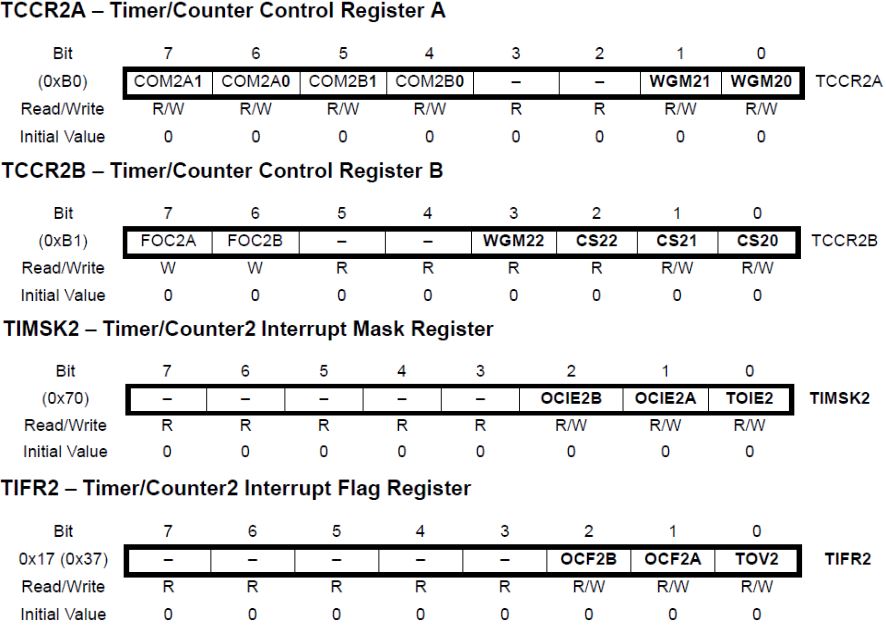
The most complicated part of using the sensor is their configuration. A timer is configured by means of its control register. Here is a reminder of the registers.
| Timer 0 | Timer 1 | Timer 2 | Rôle |
|---|---|---|---|
| TCNT0 | TCNT1L | TCNT2 | Timer (bit 0 à 7) |
| – | TCNT1H | – | Timer (bit 8 à 15) |
| TCCR0A | TCCR1A | TCCR2A | Registre de contrôle |
| TCCR0B | TCCR1B | TCCR2B | Registre de contrôle |
| – | TCCR1C | – | Registre de contrôle |
| OCR0A | OCR1AL | OCR2A | Output Compare (bit 0 à 7) |
| – | OCR1AH | – | Output Compare (bit 8 à 15) |
| OCR0B | OCR1BL | OCR2B | Output Compare (bit 0 à 7) |
| – | OCR1BH | – | Output Compare (bit 8 à 15) |
| – | ICR1L | – | Input Capture (bit 0 à 7) |
| – | ICR1H | – | Input Capture (bit 8 à 15) |
| TIMSK0 | TIMSK1 | TIMSK2 | Interrupt Mask |
| TIFR0 | TIFR1 | TIFR2 | Interrupt Flag |
The TCNTx register contains the timer/counter value, the TCCRxA and TCCRxB register are the control registers. OCRxA and OCRxB contain the register values to be compared. TIMSKx contains the interrupt mask and TIFRx contains the enable flags.
Code using timer2
For this example, we use timer2 which is coded on 8bits (256). So we have to introduce an extra counter.
unsigned long elapsedTime, previousTime;
void onTimer() {
static boolean state = HIGH;
elapsedTime=millis()-previousTime;
Serial.print(F("Set LED 13 : "));
if(state){
Serial.print(F("ON"));
}else{
Serial.print(F("OFF"));
}
Serial.print(F(" - "));Serial.print(elapsedTime);Serial.println(F("ms"));
digitalWrite(13, state);
state = !state;
previousTime=millis();
}
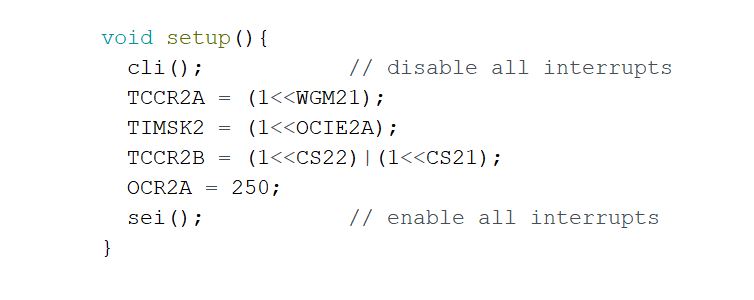
void setup(){
Serial.begin(9600);
pinMode(13, OUTPUT);
cli(); // disable all interrupts
TCCR2A = (1<<WGM21)|(0<<WGM20); // Mode CTC
TIMSK2 = (1<<OCIE2A); // Local interruption OCIE2A
TCCR2B = (0<<WGM22)|(1<<CS22)|(1<<CS21); // Frequency 16Mhz/ 256 = 62500
OCR2A = 250; //250*125 = 31250 = 16Mhz/256/2
sei(); // enable all interrupts
}
ISR(TIMER2_COMPA_vect){ // timer compare interrupt service routine
static int counter=0;
if (++counter >= 125) { // 125 * 4 ms = 500 ms
counter = 0;
onTimer();
}
}
void loop(){
}
Code using timer1
For this example, we will use the timer1
unsigned long elapsedTime, previousTime;

void onTimer() {
  static boolean state = HIGH;
  elapsedTime=millis()-previousTime;
  Serial.print(F("Set LED 13 : "));
  if(state){
    Serial.print(F("ON"));
  }else{
    Serial.print(F("OFF"));
  }
  Serial.print(F(" - "));Serial.print(elapsedTime);Serial.println(F("ms"));
  digitalWrite(13, state);
  state = !state;

  previousTime=millis();
}

void setup(){
  Serial.begin(9600);
  pinMode(13, OUTPUT);

  cli();           // disable all interrupts
  TCCR1A = 0;
  TCCR1B = 0;
  TCNT1  = 0;
  OCR1A = 31250;            // compare match register 16MHz/256/2 = 31250
  TCCR1B = (1 << WGM12);   // CTC mode
  TCCR1B = (1 << CS12);    // // Frequency 16Mhz/ 256 = 62500
  TIMSK1 = (1 << OCIE1A);  // Local interruption OCIE1A
  sei();             // enable all interrupts
}

ISR(TIMER1_COMPA_vect){          // timer compare interrupt service routine
  onTimer();
}

void loop(){
}
N.B.: We have added an elapsed time measurement for illustration purposes, but care must be taken when using interrupt-based functions in interrupt-call functions. There may be interferences.
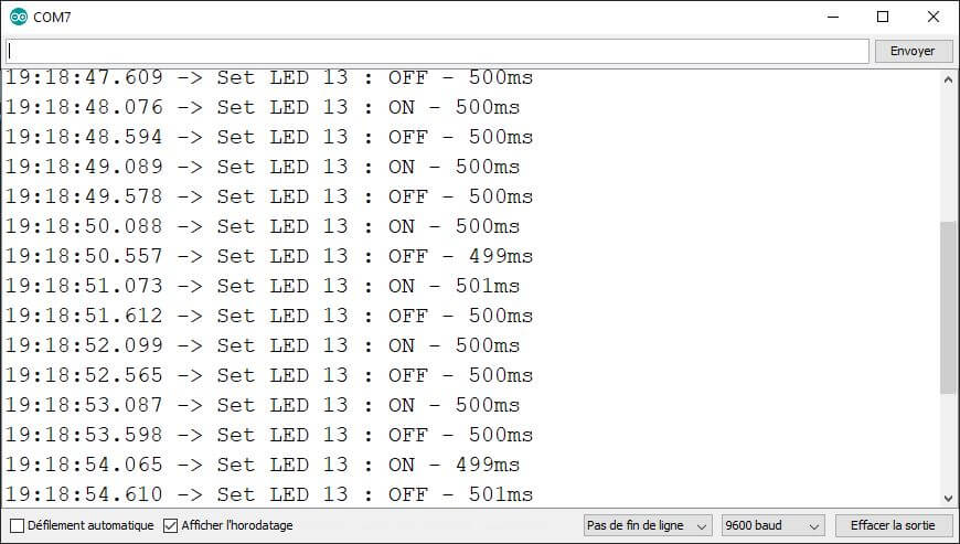
Result
Once the program is started, the on-board LED turns on and off every 500ms
Sources
Retrouvez nos tutoriels et d’autres exemples dans notre générateur automatique de code
La Programmerie


thanks alot for the important information s