In this tutorial, we go through the steps to program a TE0720, development board integrating a Xilinx Zynq-Z020 SoC, with Vivado and Vitis part of Xilinx software suite.
Material
- Computer with Xilinx Vivado 2020.2 installed
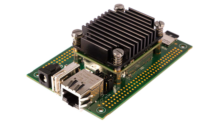
- TE0720 Starter kit
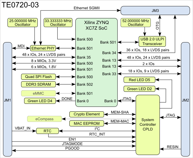
TE0720 Overview
The Trenz Electronic TE0720 is an industrial-grade SoM (System on Module) based on Xilinx Zynq-7000 SoC with up to 1 GB of DDR3/L SDRAM, 32MB of SPI flash memory, Gigabit Ethernet PHY transceiver, a USB PHY transceiver and powerful switching-mode power supplies for all on-board voltages. A large number of configurable I/Os is provided via rugged high-speed stacking strips.
Key Features:
- Xilinx XC7Z SoC (XC7Z020 or XC7Z014S)
- 54 multiuse I/O (MIO) pins
- 152 High-Range (HR) I/O pins (SelectIO interfaces)
- System Controller CPLD (Lattice LCMXO2-1200HC)
- Up to 1 GByte DDR3/L SDRAM memory (2 x 256 Mbit x 16, 32-bit wide data bus).
- 32 MByte Quad SPI Flash memory
- Gigabit Ethernet transceiver PHY (Marvell 88E1512)
- MAC address serial EEPROM with EUI-48™ node identity (11AA02E48)
- Highly integrated full-featured hi-speed USB 2.0 ULPI transceiver (Microchip USB3320C-EZK)
- 3-axis accelerometer and 3-axis magnetometer (ST Microelectronics LSM303DTR) (Optional!)
- Real time clock with embedded crystal (Intersil ISL12020M): ±5ppm accuracy
- Atmel CryptoAuthentication element (Atmel ATSHA204A)
- Up to 32 GByte eMMC, usually 4 GByte, depends on module variant and assembly option
- User LED 1 (Green), user LED 2 (Red), user LED 3 – FPGA DONE (Green)
- On-board high-efficiency DC-DC converters for all voltages used
- Trenz 4 x 5 module socket connectors (3 x Samtec LSHM series connectors)
Installation of Xilinx software
Download and install Xilinx as self-extract or Single-file donwload
N.B.: You need at least 50 Gb of memory to install Xilinx
Project Creation
Create new project and select a name like tutoTE0720
Navigate to Default parts section. In Tab Boards, press on “Install/Update Boards”
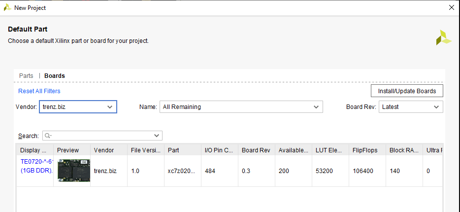
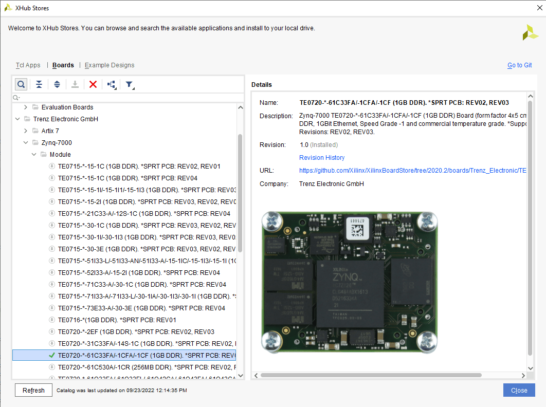
This will configure the project specificallly for the board
Create first design
Click on create design.
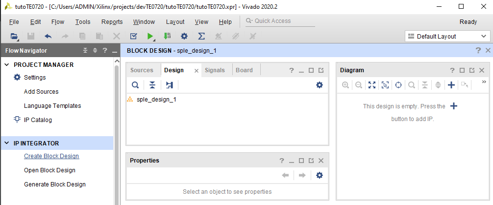
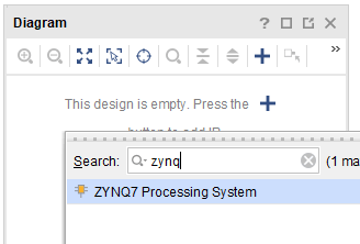
In tab Diagram, click on the plus sign “+” to add IP. Search for Zynq7
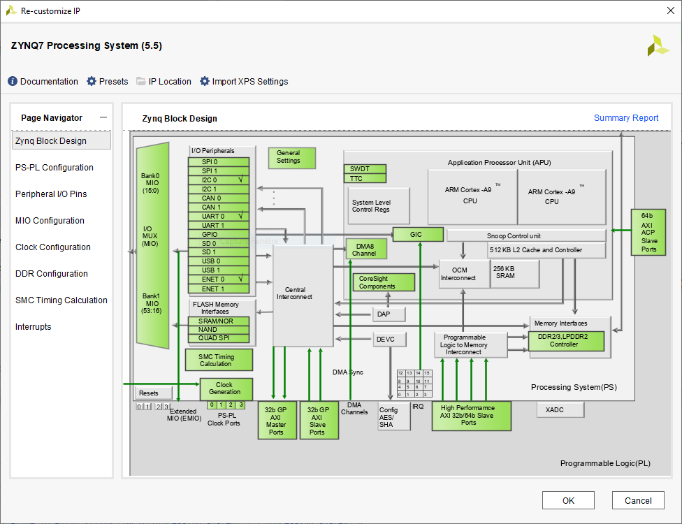
Double-click on block to configure IP and modify parameters to add the required functionalities .
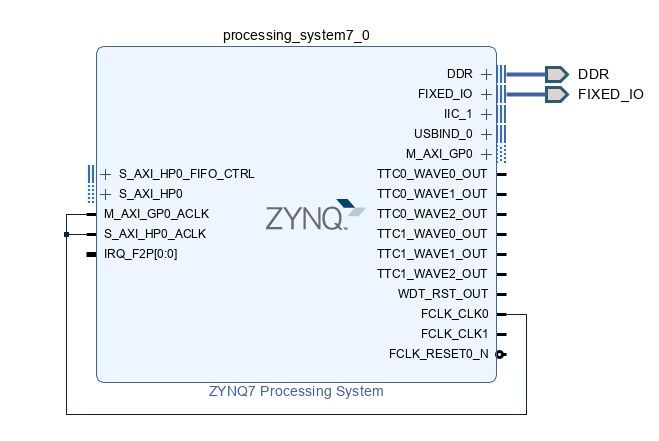
Then click on Run Block Automation to complete diagram automatically. Once the DDR and FIXED_IO outputs are set, you can add the missing connection.
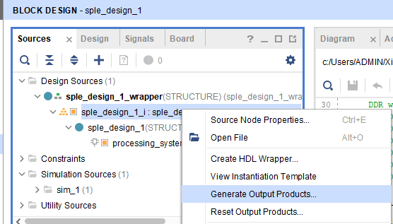
then right click on design and select Generate output products
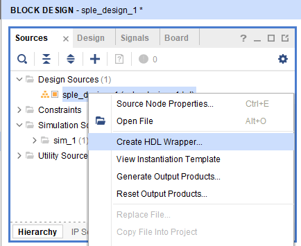
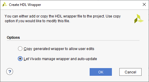
Finally right-click on design again and select “Create HDL wrapper…” .and chose let Vivado manage.
Once your design is complete and the wrapper generated, you can go through implementation
Get ready for implementation
The complete implementation process is divided in three process: Synthesis, Implementation and bitstream generation.
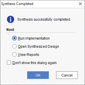
In the right menu, “Run Synthesis”
Wheen asked, select “Run Implementation”
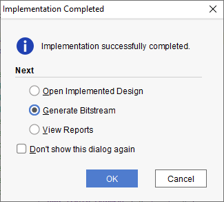
“Generate bitstream”
Program device using Vivado
Once the bitstream is generated, you can proceed to device programmation.
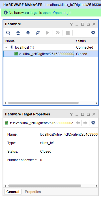
Open Hardware Manager and Open Target (in the green highlighted info bar)
Program Device in the right menu
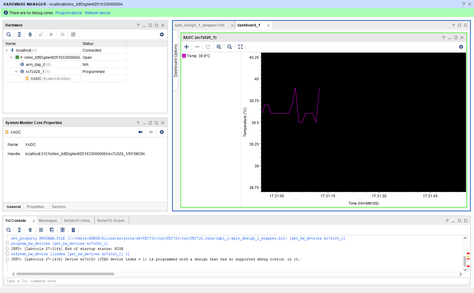
Temperature from Zynq is displayed in dashboard tab. TE0720 device was programmed using the Vivado software.
Program CPU
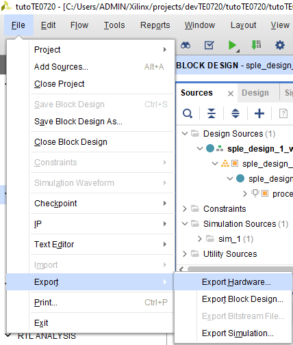
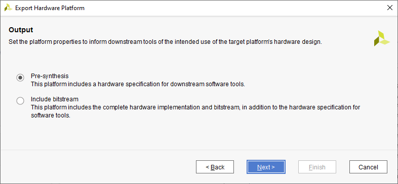
Select file>Export>Export Hardware…
Select option Pre-synthesis
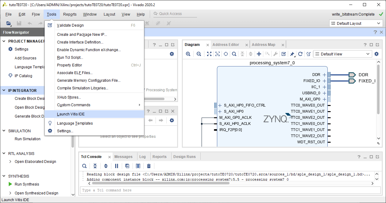
Then Tools> Launch Vitis IDE
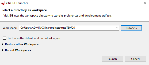
Select same workspace as Vivado project
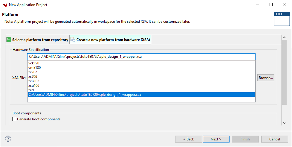
Create platform from XSA generated by Vivado by browsing to the XSA file in Vivado project created in the Export Hardware step.
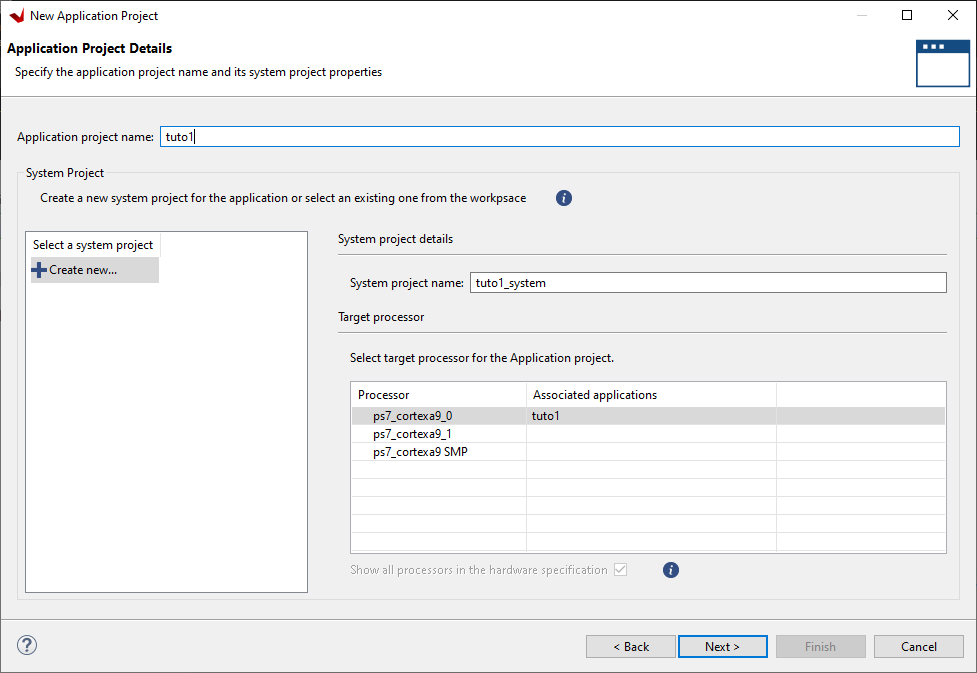
Choose application name and target core
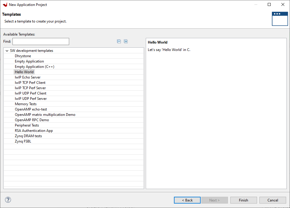
Choose template
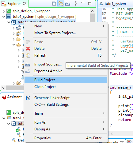
Once the program is coded properly, you can select “Build Project”
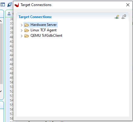
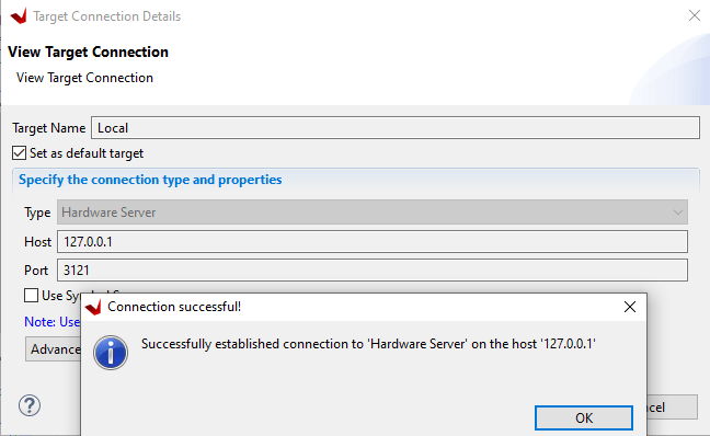
You can test the connexion to hardware clicking on the task bar icon
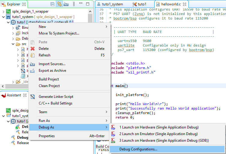
If the hardware is properly connected, you can start debuggig by navigating to “Debug As”
Once debug is started, you can see that the program is running on the CPU. To be abble to debug and see the message in the terminal, one step is missing.
Debug from Vitis Serial Console
To observe debug messages(printf) from the Zynq board, you can use the Vitis Serial Console. Click on the plus sign and select the serial port connected to the Zynq board.
Debug project in JTAG Terminal
In order to see the printf messages, we need to route the stdout output to coresight
Disconnect board to stop the program in debug tab
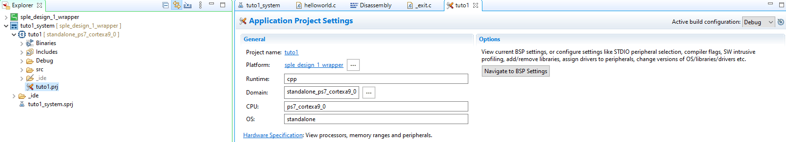
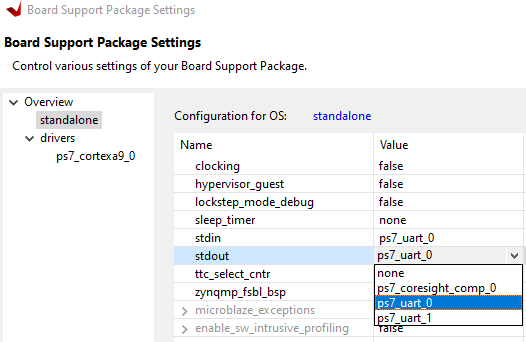
Go back to Design tab and open project settings (double click on <tutorial-name>.prj). Then click On “Navigate to BSP Settings”
And “Modify BSP Settings…”
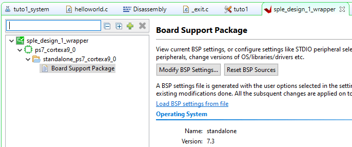
Navigate to standalone and change stdin and stdout from ps7_uart_0 to ps7_coresight_comp_0
To apply the changes, the project should be build again. Then click on Debug As
In the XSCT Console, enter the following command to open the terminal
jtagterminal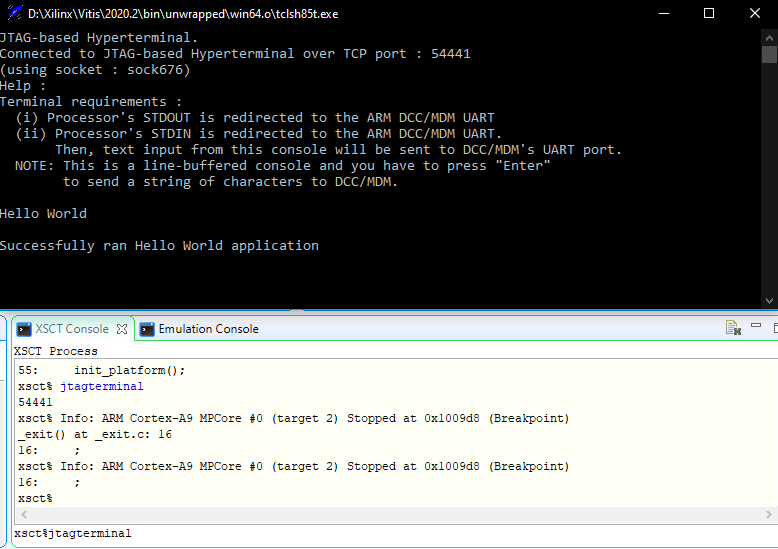
You can see the message from the code displayed in the terminal. Proof that the TE0720 was successfully programmed by Vitis.


