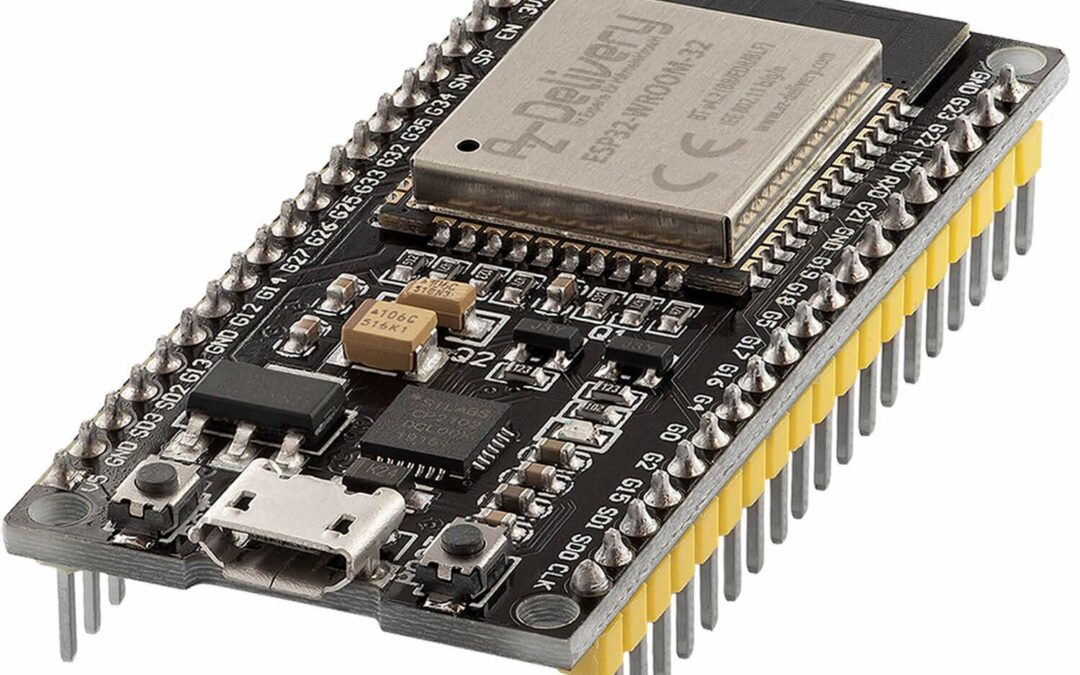
NodeMCU ESP32 is a microcontroller with integrated WiFi and Bluetooth modules. Very easy to use, it’s lightweight and has a memory and calculation capacity superior to that of the Arduino. This makes it an ideal board for learning programming, developing connected objects or servers.
Microcontroller features
The NodeMCU ESP32 microcontroller uses the ESP-WROOM-32 microprocessor (Tensilica Xtensa LX6). This processor operates at a clock frequency of 240 MHz, with 520 kB RAM, 448 kB EEPROM and 4000 kB Flash memory (for programming and data logging).
|  |
The microcontroller has a WiFi chip, enabling it to connect to the local network, create a server or create its own network for other devices to connect to. The microcontroller has a Bluetooth chip that enables it to interact with other devices.
Power supply
The NodeMCU ESP32 microcontroller operates over a voltage range of 7-12V, thanks to its on-board voltage regulator, while the microprocessor operates with a voltage of 3.3V. In normal operation, the microcontroller consumes up to 45mA (if no power is supplied) and can accept a maximum current of 40mA on each of its IO pins.
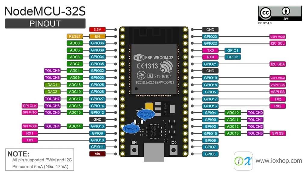
Pinout
- Analog I/O : 15 (2, 4, 12, 13, 14, 15, 25, 26, 27, 32, 33, 34, 35, 36, 39)
- Digital I/O : 4 (all except 6 to 11)
- PWM pins: 16 (2, 4, 5, 6, 12, 13, 14, 15, 18, 19, 21, 25, 26, 27, 32, 33)
- Communication Série : 9 (1, 2, 3, 4, 5, 12, 13, 14, 15)
- I2C communication : 1 ((’21’, ’22’))
- SPI communication: 1 ((‘5′, ’18’, ’19’, ’23’))
- I2S communication: 1 ((’26’, ’25’, ’33’))
- Touch: 9 (2, 4, 12, 13, 14, 15, 27, 32, 33)
- Interrupt: 26 (0, 1, 2, 4, 5, 7, 12, 13, 14, 15, 16, 17, 18, 19, 21, 22, 23, 25, 26, 27, 32, 33, 34, 35, 36, 39)
Basic code and pin identification
const int analogPin=34; // 2, 4, 12, 13, 14, 15, 25, 26, 27, 32, 33, 34, 35, 36, 39
const int digitalInPin=2; // all except 6 to 11
const int digitalOutPin=4; // all except 6 to 11 and 34, 35, 36 and 39 inputs only
const int pwmPin=3; // broches 2, 4, 5, 6, 12, 13, 14, 15, 18, 19, 21, 25, 26, 27, 32, 33

int analogVal=0;
int digitalState=LOW;
int pwmVal=250;

// setting PWM properties
const int freq = 5000;
const int ledChannel = 0;
const int resolution = 8;

void setup() {
  Serial.begin(115200);

  pinMode(analogPin,INPUT); // broches 0-13 et 14-19, Argument OUTPUT, INPUT
  pinMode(digitalInPin,INPUT);
  pinMode(digitalOutPin,OUTPUT);

  ledcSetup(ledChannel, freq, resolution);
  ledcAttachPin(pwmPin, ledChannel);
}

void loop() {
 analogVal=analogRead(analogPin); //  return int
 digitalState=digitalRead(digitalInPin); //  return boolean
 digitalWrite(digitalOutPin,HIGH); // valeur LOW(0) ou HIGH(1)
 ledcWrite(ledChannel, pwmVal);// valeur 0-255
}
For more information on the use of pins, please visit the ESP32 Pinout Reference website.
Summary of features
| Microcontrôleur | |
| Nom: | ESP32 |
| Marque: | Espressif |
| Caractéristiques | |
| CPU: | ESP-WROOM-32 (Tensilica Xtensa LX6) |
| Tension d’alimentation : | 7-12V |
| Tension logic: | 3.3V |
| E/S digitales: | 14 |
| Entrées analogiques: | 6 |
| Flash: | 4000kB |
| SRAM: | 520kB |
| EEPROM: | 448kB |
| Fréquence d’horloge: | 240 MHz |
| Wifi: | Yes |
| Bluetooth: | Yes |
| SD card: | No |
| Touch: | Yes |
| UART/SPI/I2C/I2S: | Yes/Yes/Yes/Yes |


