To control a large number of servomotors with Arduino, or other microcontroller, a servomotor driver need to be used in order to power and to send the PWM signals to the Servomotors. Several methods can be used such as using a breakout shield or a serial servo controller but you may want a particular configurations. In this tutorial, you will learn how to make your own servo driver which will let you manage sensors and/or servos as you like.
Material
- Flat pliers
- Cutter
- Soldering iron
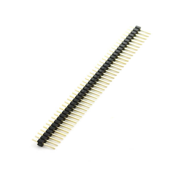
- Break away header• fils de connexion
- Perforated experimental board
- Connector for the battery
Procedure
1. Perforated experimental board
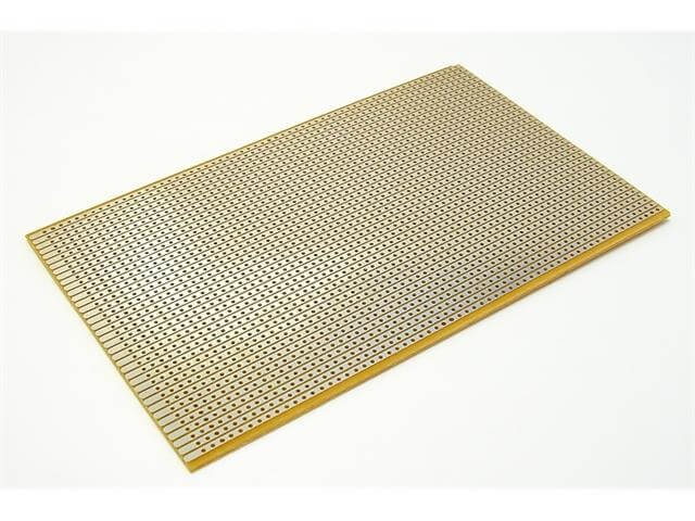
In this tutorial, the perforated board tracks have a line pattern. This pattern can be modified depending on the one you use.
Cut the board to the desired size. Be sure to keep the correct number of holes. Draw a line with the cutter between the holes you want to cut out. This will weaken the plastic and allow for a precise cut.
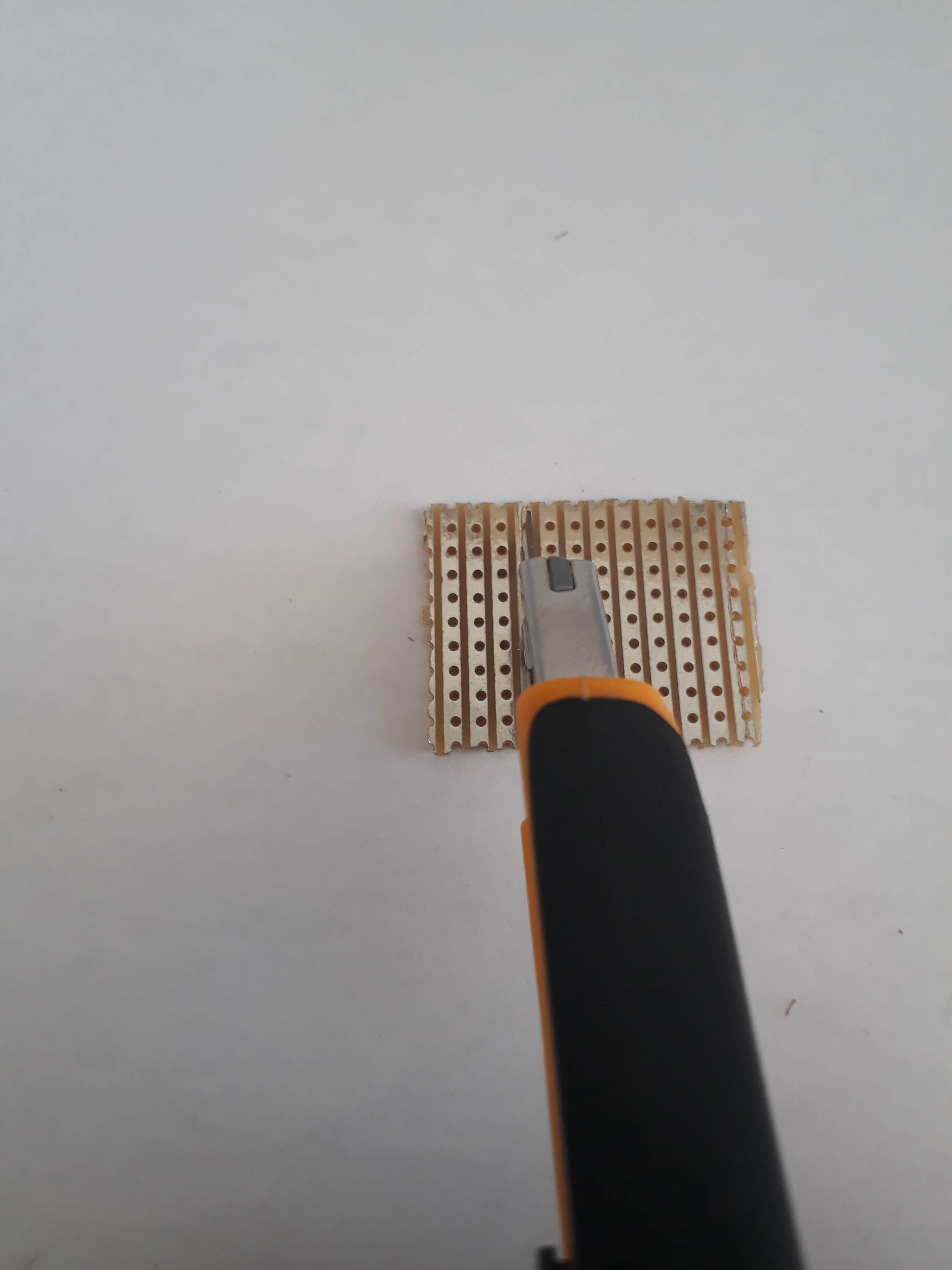
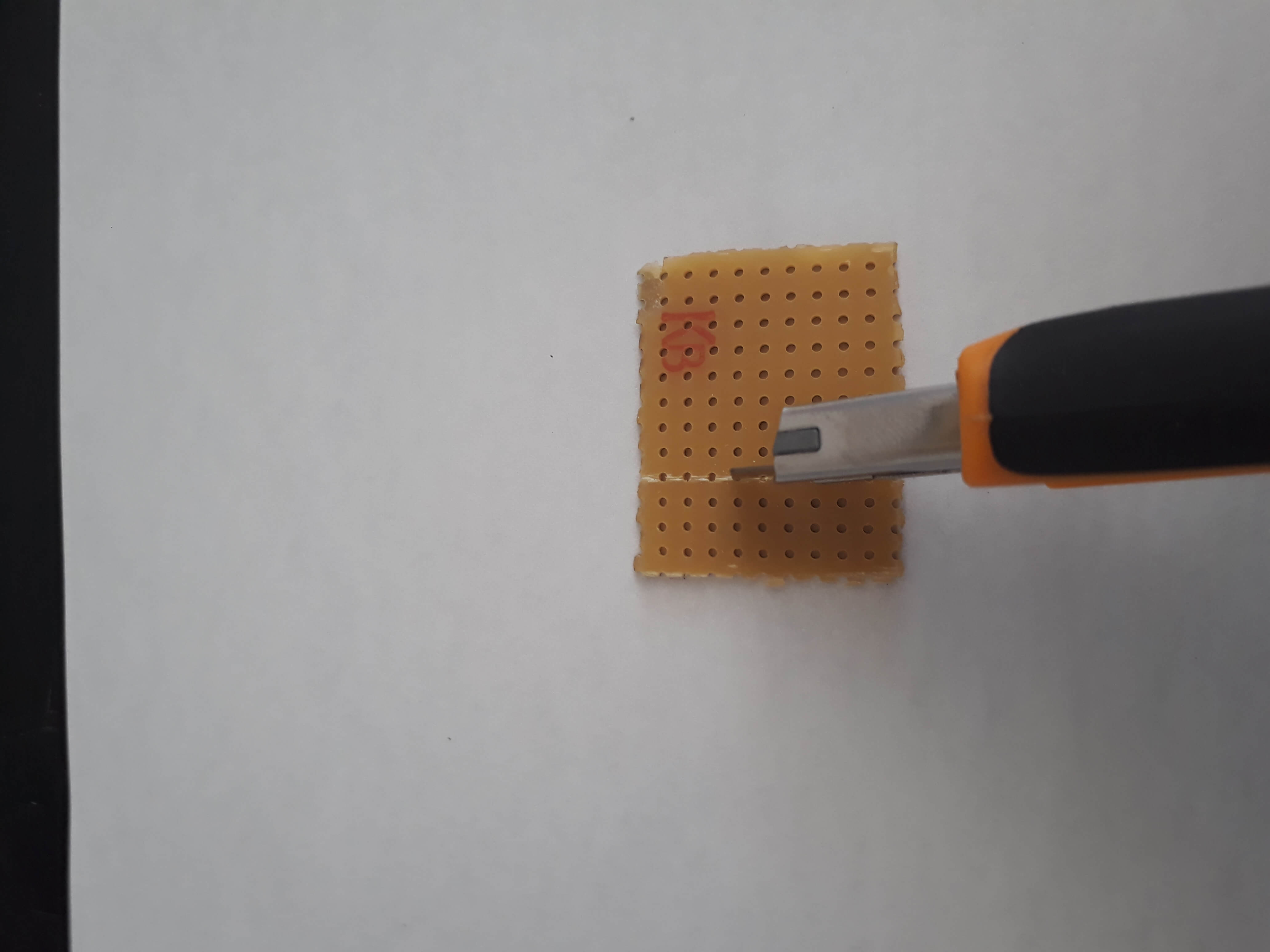
Use the pliers to split the board.
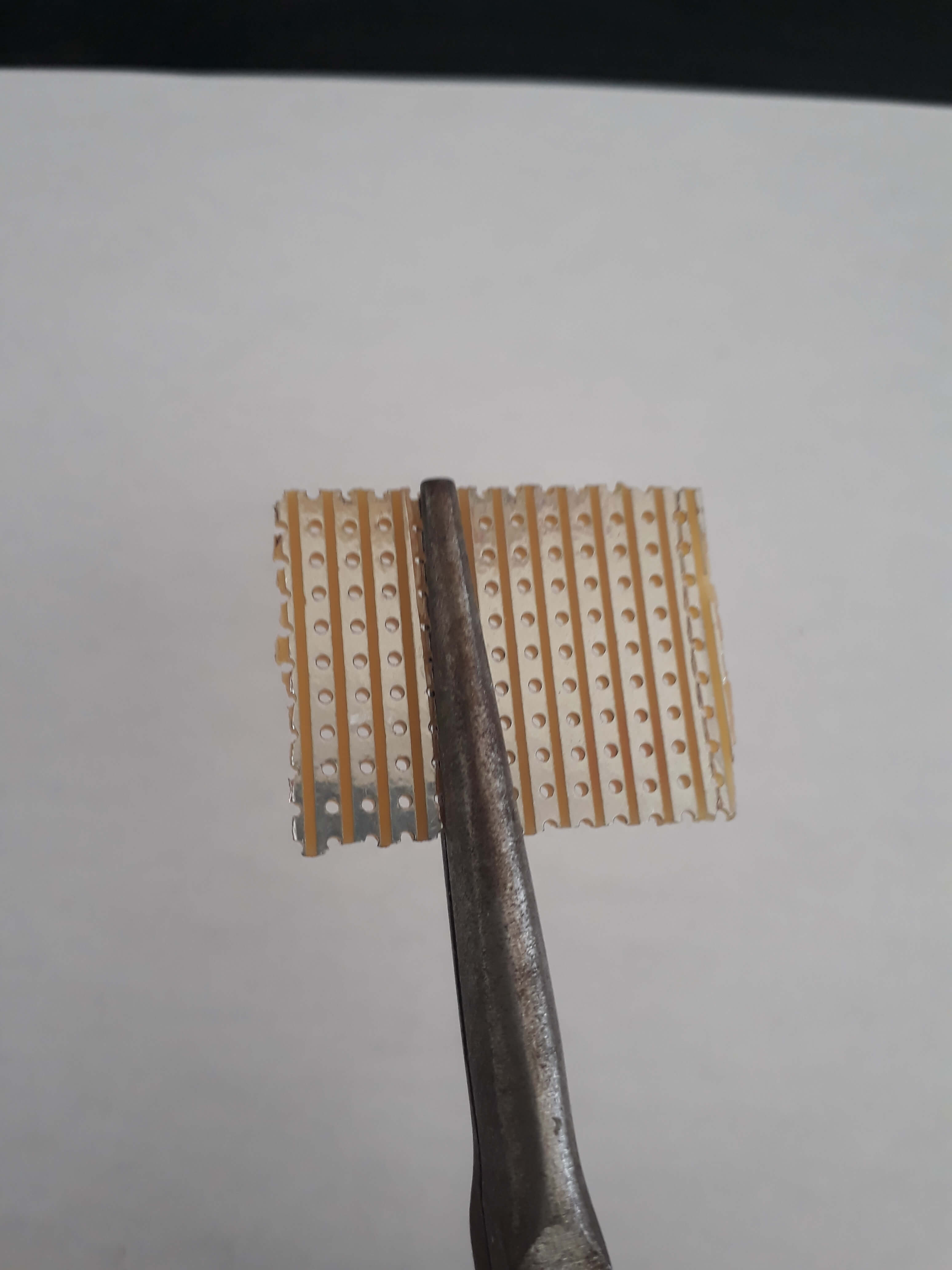
Once the experimental board is cut, you can remove the remaining copper on the side using the cutter or a flat file.
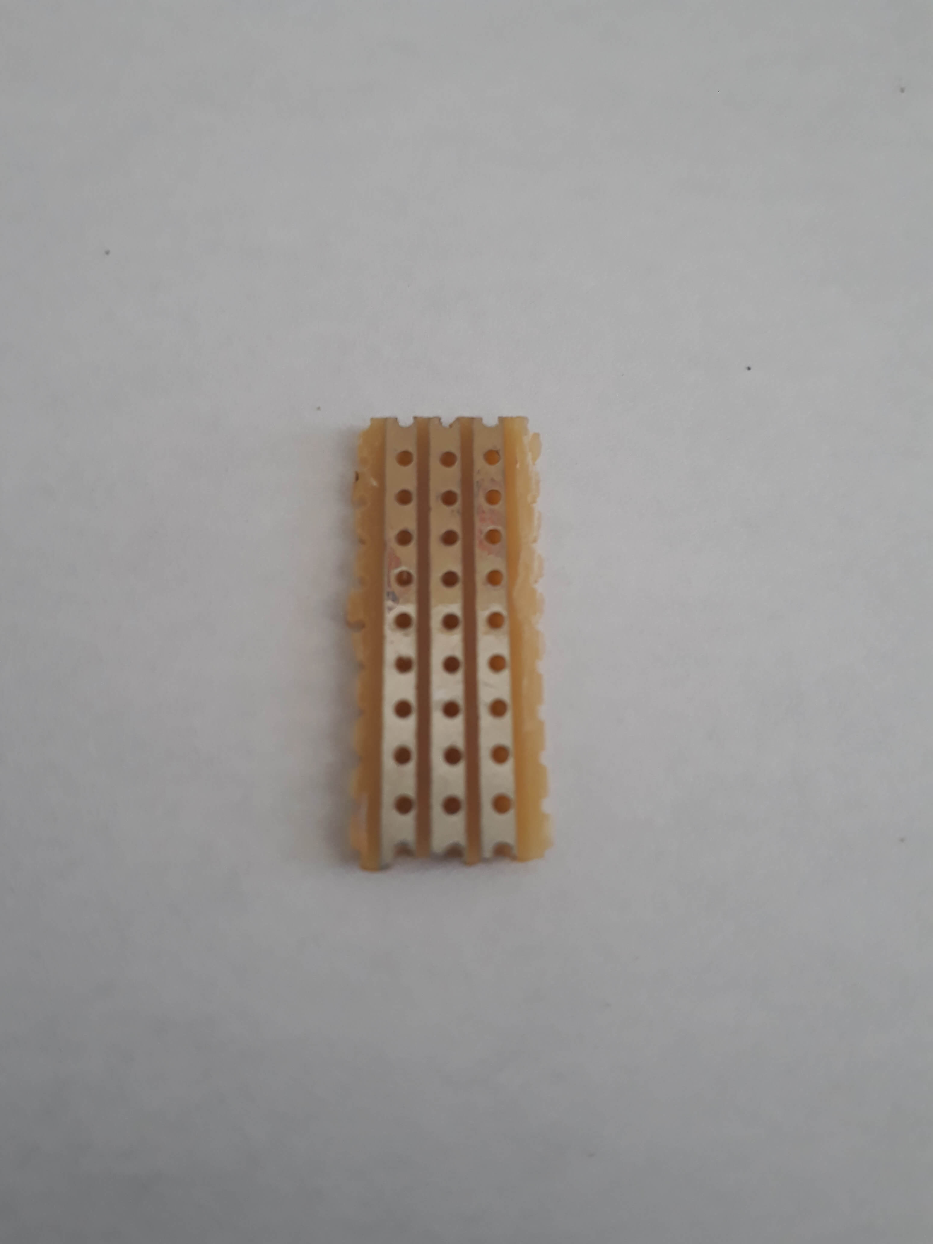
With the cutter, remove the copper between the holes where will be plugged the PWM outputs to ensure electrical isolation.
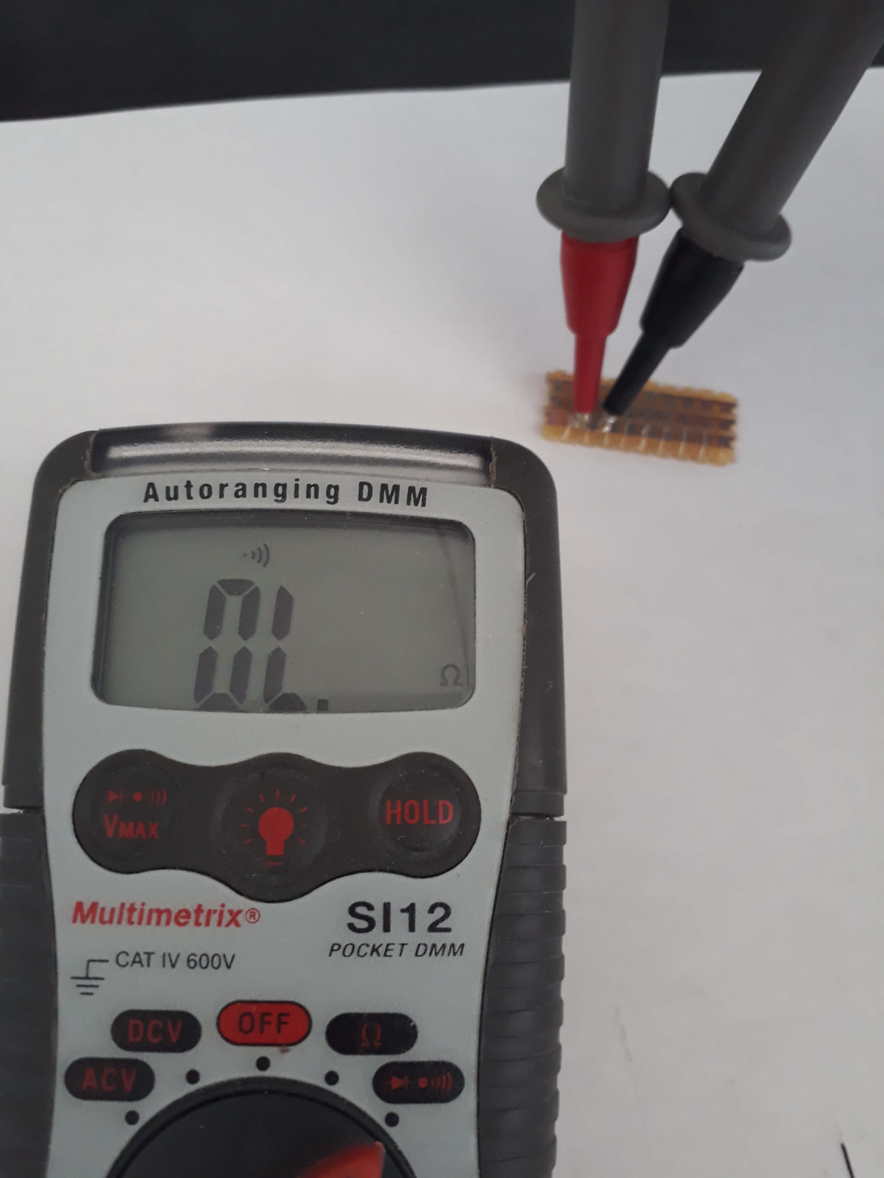
To check the isolation between the tracks, you can use a multimeter.
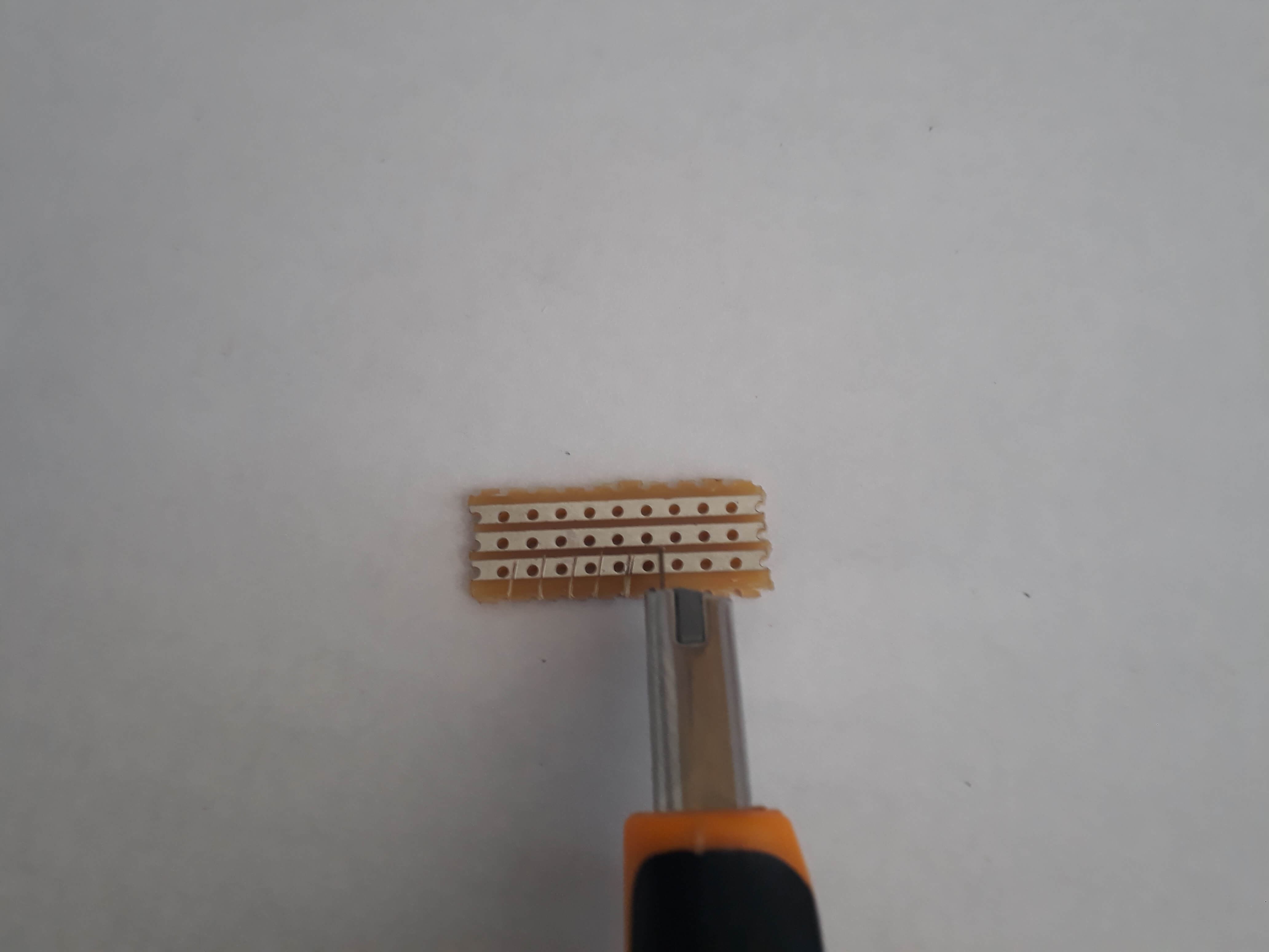
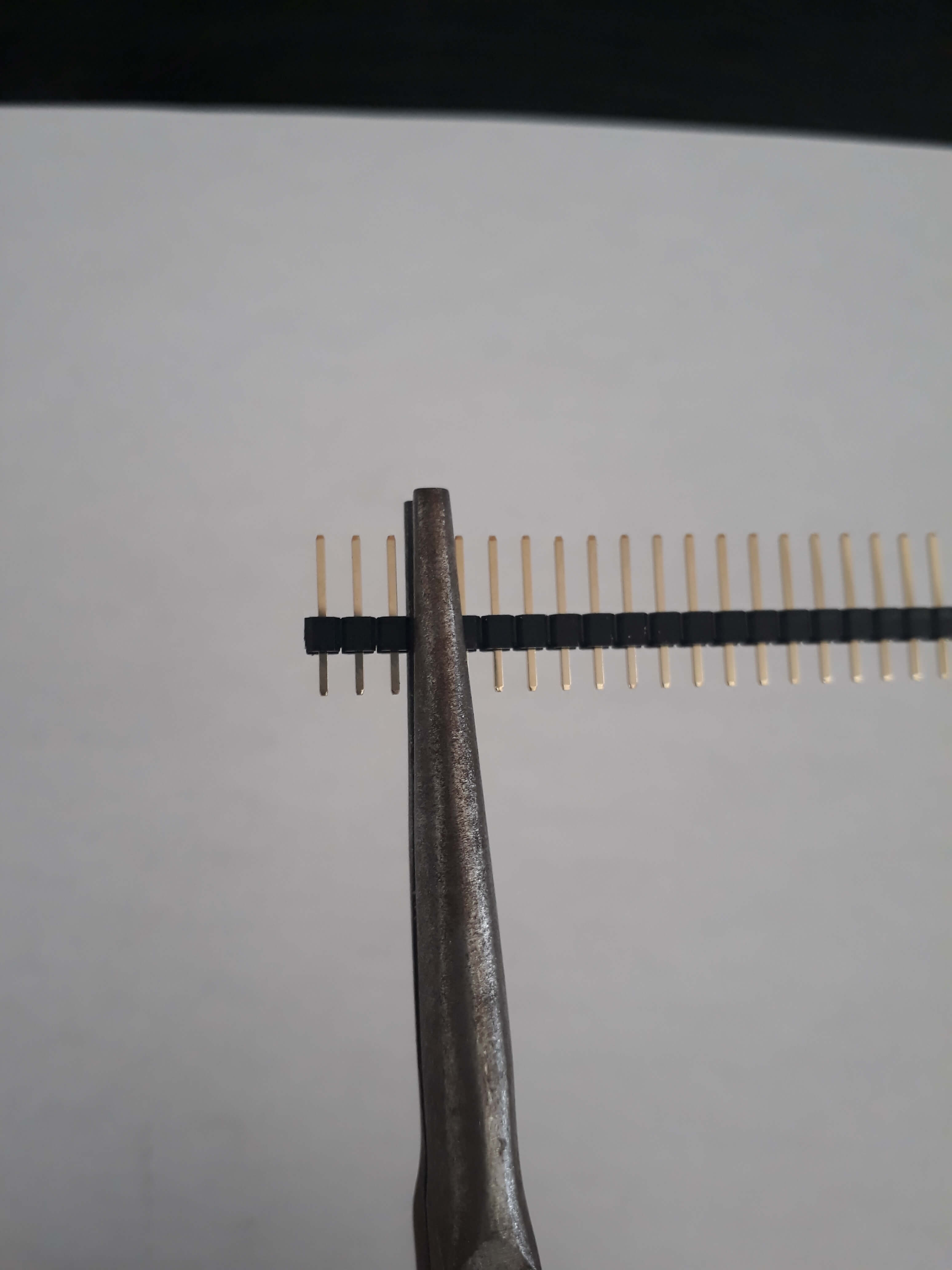
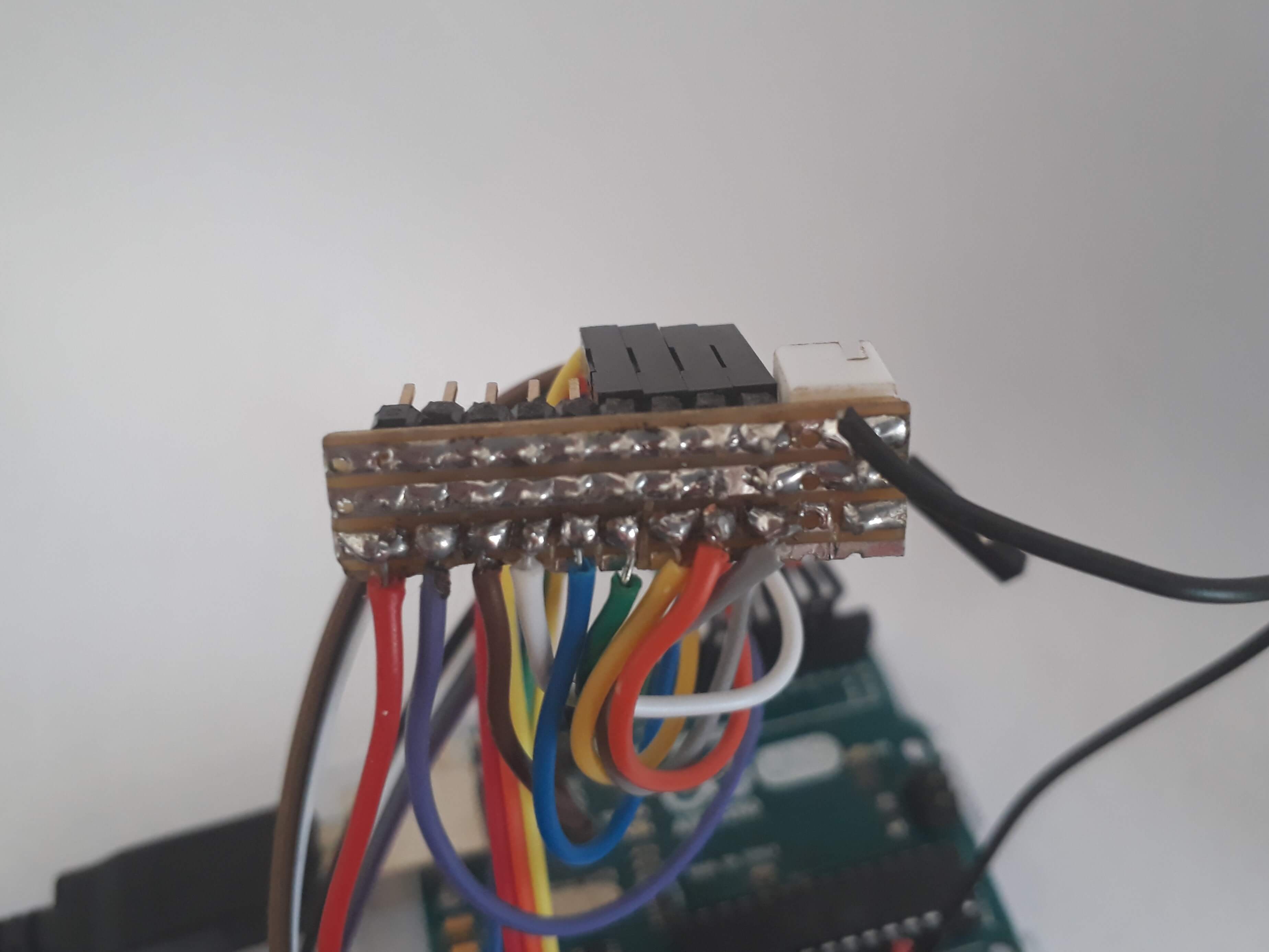
2. Break away header
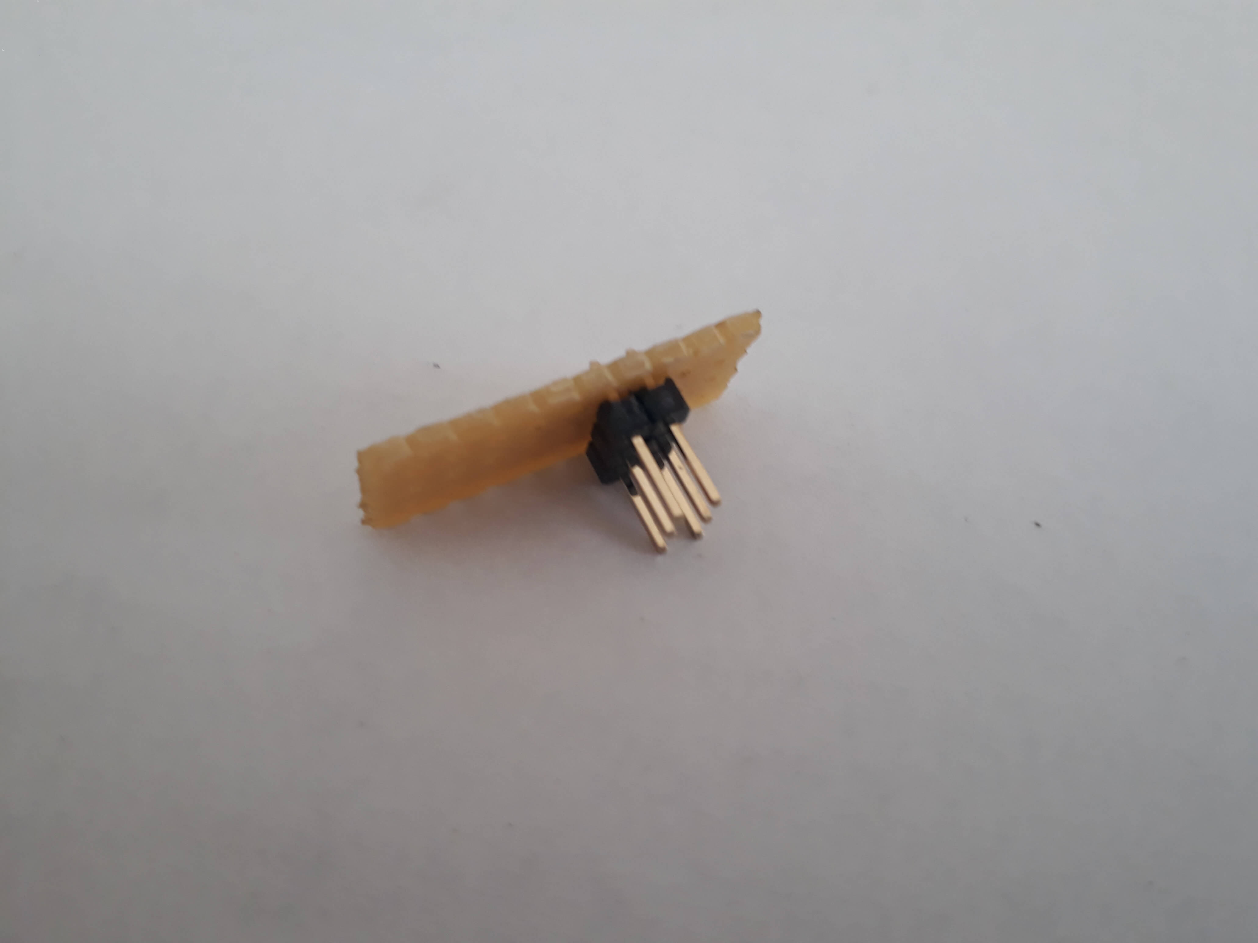
Cut the pin header by group of three with the flat pliers. Take as much as you need for servomotor or sensor. Remember that the number of servomotor you can control is limited to the number of PWM outputs of your board.
You can easily control 12 servos with an Arduino UNO.
Solder the pins as shown in the following pictures.

Once you are done soldering, check the isolation between tracks.
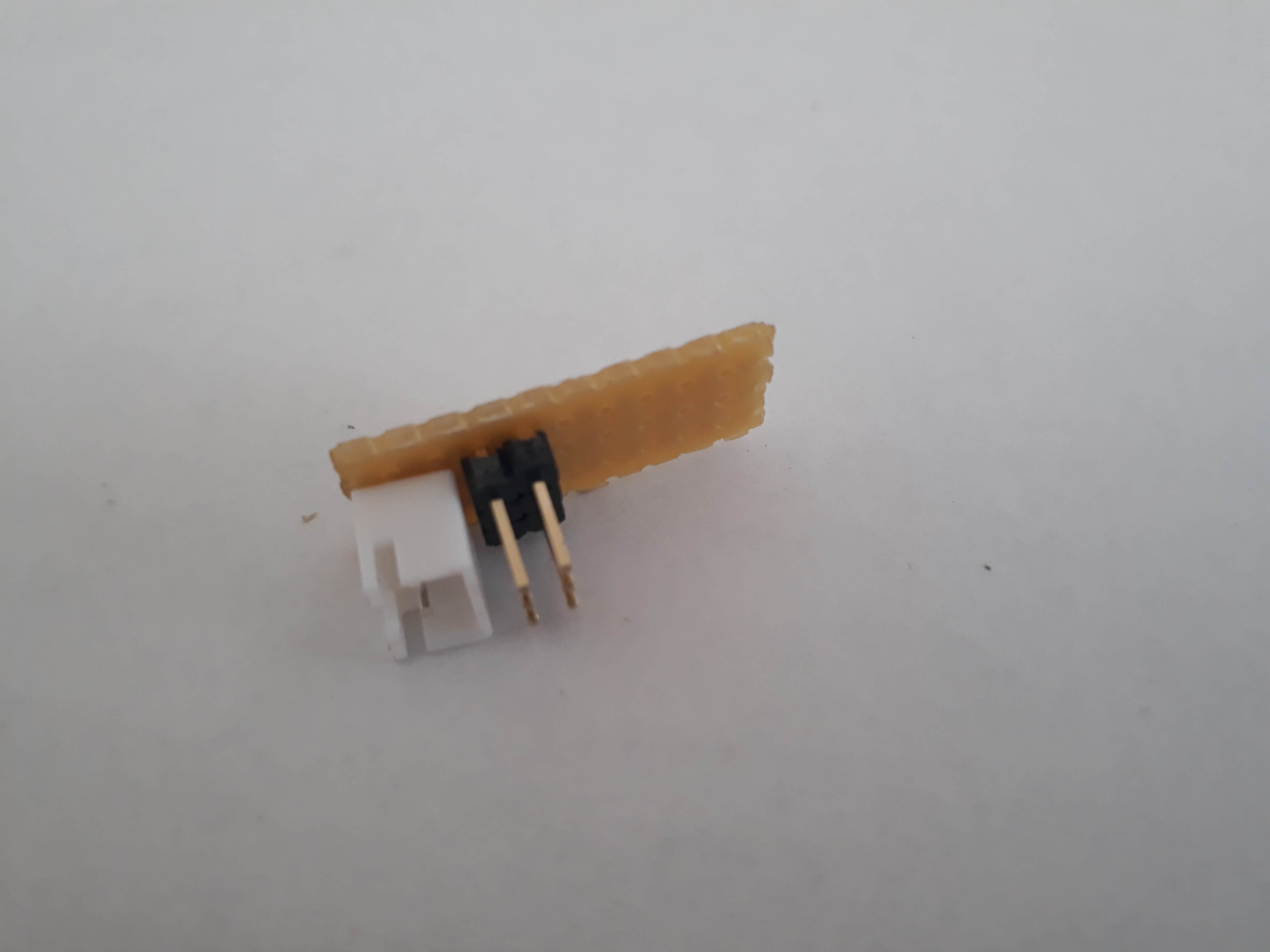
3. Battery connection
Add a connector to the board that correspond to the type used by the battery. For this project, we use a JST connector which is widely use for LiPo batteries.
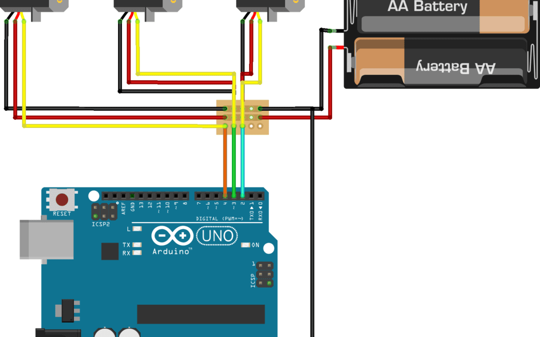
4. Wiring
Solder the wires to the pin header that will be connected to the Arduino PWM output or analog input. Solder the ground of the battery to a wire that will be connected to the ground pin of the Arduino.
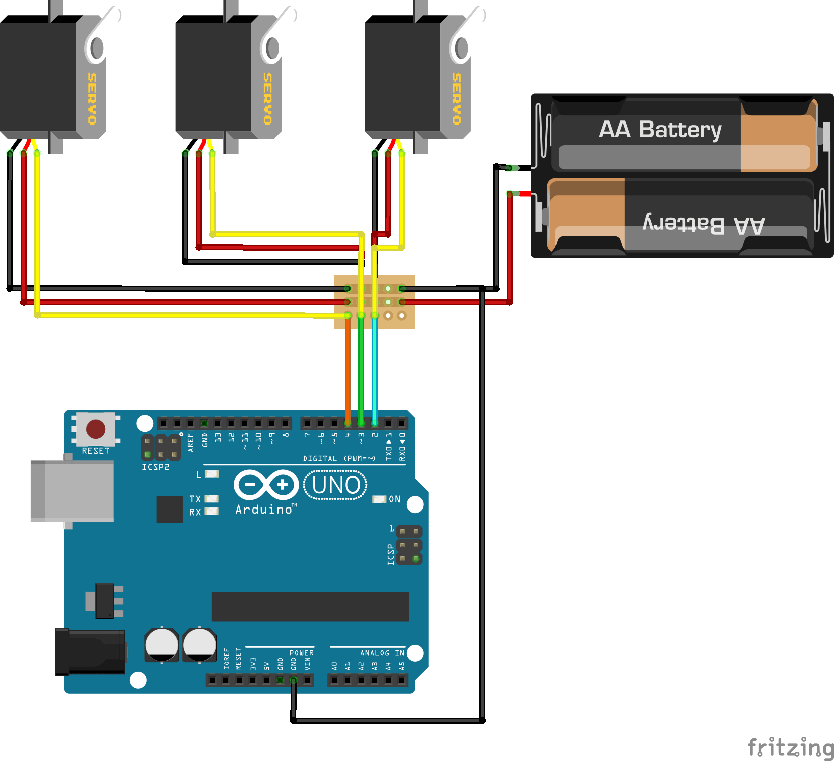
Your servomotor driver is ready to use.
Result
Precaution
1. Check component connection
2. Unplug battery after use
3. Unplug battery if servomotor are vibrating or heating abnormally.
4. It is possible to power one or two servomotors with the 5V output from the Arduino for testing purpose. Do not try to control a larger number of servo for an extended period of time. You may damage the Arduino board
5. Check servomotor wiring
Advice
When you want to control a large number of servomotor or if you are using a battery with higher voltage than what is acceptable by the servos, it is good practice to add a voltage regulator to the servomotor driver.
To learn how to program your Arduino to control servomotors, check this tutorial.
Sources
https://www.instructables.com/id/How-to-cut-pin-headers/
Find perforated board references:
https://www.digikey.fr/products/fr/prototyping-products/prototype-boards-perforated/636
https://www.instructables.com/id/Slice-Circuit-Boards-with-a-Paper-Cutter/


Thank you
Can we connect to mains with DC Adapter?
Yes, of course. Be careful to adapt the voltage to your servomotors and to check the current limit of the board.
a simple servo shield will serve the purpose
Indeed! or a Serial Servo Controller. But sometimes, you need to create your own shield and you can start with this one.