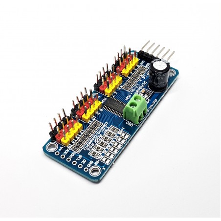
The PCA9685 module is a 16-channel controller that can control 16 PWM outputs via I2C communication. Among other things, it allows you to free up inputs and outputs of your microcontroller and drive up to 16 LEDs or servomotors (or any other module taking a PWM signal as input) using two pins (SCL and SDA) while keeping the pins of your microcontroller for other modules such as sensors. The Raspberry Pi is a microcontroller with integrated Bluetooth and Wifi modules. Very easy to use, it is lightweight and has a higher memory and computing capacity than the Arduino. We will see in this tutorial how to drive several servomotors with a Raspberry Pi and a PCA9685 module.
Prerequisite : Configuration of the Raspberry Pi in I2C
Hardware
- Ordinateur
- RapsberryPi3B+
- PCA9685Module
Principle of operation
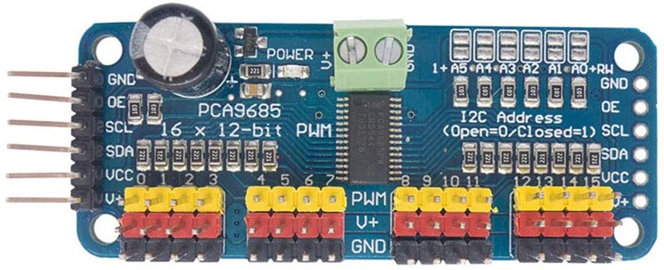
The module is based on the PCA9685 controller, which allows PWM outputs to be controlled using I2C communication and an integrated clock. The module has 6 bridges to select the address of the board and thus allow up to 62 controllers to be placed on the same bus for a total of 992 servomotors (addresses available 0x40 to 0x7F).
It can drive PWM outputs with adjustable frequency and 12-bit resolution. The module is compatible with 5V and 3.3V microcontrollers.
Schematic
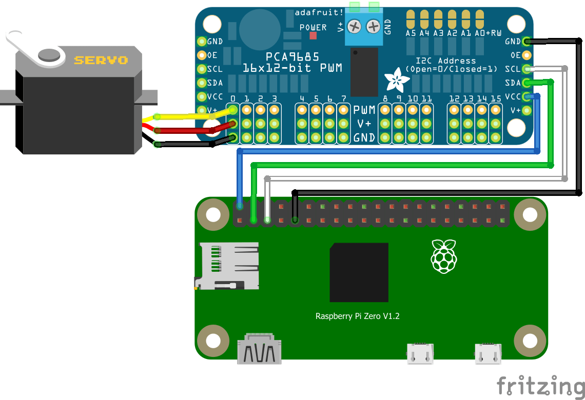
The Raspberry Pi has dedicated pins for I2C communication (GPIO2/GPIO3).
The module is equipped with an I2C bus and a power input. The I2C bus is connected as follows:
- GPIO3 or SCL pin to the SCL pin of the module
- GPIO2 or SDA pin to the SDA pin of the module
- 5V pin to Vdc pin of the module
- GND pin to GND pin of the module
In this tutorial we use the Raspberry Pi Zero card but it can be adapted to other microcontrollers. All that is required is to adapt the I2C pins available on the microcontroller in question and possibly the code.
Code
Library installation
To use the PCA9685 module we use the following library adafruit_servokit.h. This library is not present by default in the Python installation. To install it, simply open a terminal and enter the following command line.
sudo pip3 install adafruit-circuitpython-servokitScript Python
PWM widths are usually given in microseconds over a period of 20ms (50Hz) but these values can vary from one servo motor to another and between suppliers. You will need to modify the code values to suit your servomotor. In our case, we use the MG90S servomotor with pulse widths between 500 and 2500µs over 20ms.
#!/usr/bin/env python
# -*- coding: utf-8 -*-

#Libraries
import time	#https://docs.python.org/fr/3/library/time.html
from adafruit_servokit import ServoKit	#https://circuitpython.readthedocs.io/projects/servokit/en/latest/

#Constants
nbPCAServo=16

#Parameters
MIN_IMP  =[500, 500, 500, 500, 500, 500, 500, 500, 500, 500, 500, 500, 500, 500, 500, 500]
MAX_IMP  =[2500, 2500, 2500, 2500, 2500, 2500, 2500, 2500, 2500, 2500, 2500, 2500, 2500, 2500, 2500, 2500]
MIN_ANG  =[0, 0, 0, 0, 0, 0, 0, 0, 0, 0, 0, 0, 0, 0, 0, 0]
MAX_ANG  =[180, 180, 180, 180, 180, 180, 180, 180, 180, 180, 180, 180, 180, 180, 180, 180]

#Objects
pca = ServoKit(channels=16)

# function init
def init():

	for i in range(nbPCAServo):
		pca.servo[i].set_pulse_width_range(MIN_IMP[i] , MAX_IMP[i])


# function main
def main():

	pcaScenario();


# function pcaScenario
def pcaScenario():
	"""Scenario to test servo"""
	for i in range(nbPCAServo):
		for j in range(MIN_ANG[i],MAX_ANG[i],1):
			print("Send angle {} to Servo {}".format(j,i))
			pca.servo[i].angle = j
			time.sleep(0.01)
		for j in range(MAX_ANG[i],MIN_ANG[i],-1):
			print("Send angle {} to Servo {}".format(j,i))
			pca.servo[i].angle = j
			time.sleep(0.01)
		pca.servo[i].angle=None #disable channel
		time.sleep(0.5)


if __name__ == '__main__':
	init()
	main()
Applications
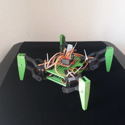
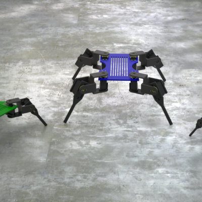
- Controlling the Quadrina6 robot
Sources
- http://adafruit.github.io/Adafruit-PWM-Servo-Driver-Library/html/class_adafruit___p_w_m_servo_driver.html#aa892432ed08e4b3892c8eb0478168dd8
- https://robojax.com/learn/arduino/robojax-PCA6985.pdf
- https://www.nxp.com/products/power-management/lighting-driver-and-controller-ics/ic-led-controllers/16-channel-12-bit-pwm-fm-plus-ic-bus-led-controller:PCA9685
- https://docs.python.org/fr/3/library/time.html
- https://circuitpython.readthedocs.io/projects/servokit/en/latest/
Hello, I am using a 360° Servomotor should i then use 360 for MaxAngle right?
Usually, 360° servomotor are continuous rotation motor. Therefore PWM value control the speed of the servomotor not the position.
You should use the function kit.continuous_servo[1].throttle to control available in the library to control the speed of the servo
kit.continuous_servo[1].throttle = 1 (full speed forward)
kit.continuous_servo[1].throttle = -1 (full speed backward)
kit.continuous_servo[1].throttle = 0.5 (half speed forward)
Hi, thanks for contributing your work. I have several problems:
1. I get an error from adafruit_servokit package: module board has no attribute I2C
2. I do not see any place where I can set the address of my PCA9685
what shall I do?
Thanks for your comment
1. You need to enable I2C communication in the Raspberry Pi configuration
2. When initializing the ServoKit object class pca=ServoKit(channels=16, address=41)
class adafruit_servokit.ServoKit(*, channels, i2c=None, address=64, reference_clock_speed=25000000, frequency=50)
Hi, thanks for contributing your work. I have several problems:
1. As a result of operating by adjusting the pulse value for my motor, the initial position was fixed from 20 degrees to 170 degrees. How to solve it?
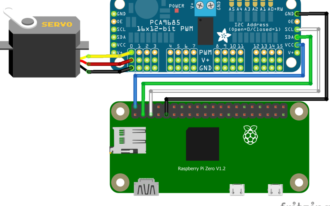
Wiring in the diagram is wrong VCC om the board should go to 3.3V on the Raspberry though 5V could damage the board.
Hello,
PCA9685 logic electronic can run with 3.3V or 5V from Raspberry Pi without damage. Power circuit (V+) should be a different supply.