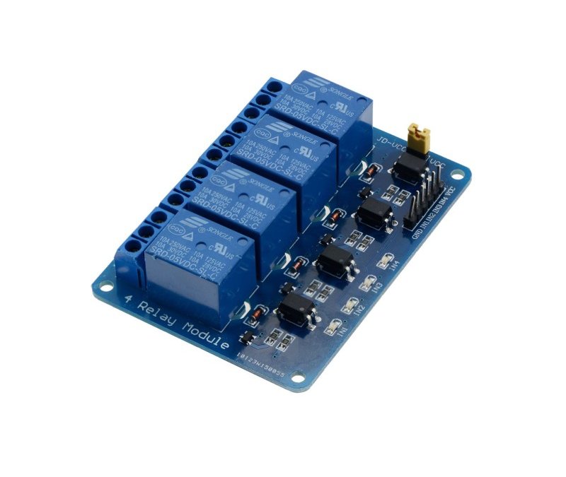
When developing a home automation system, it is common to use a multi-channel relay module. These modules have several relay outputs (2, 4, 8 or 16) and offer an easy connection. This makes it possible to control several devices with a single microcontroller.
Material
- Computer
- Arduino UNO
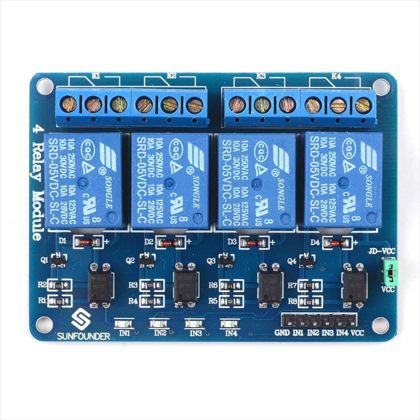
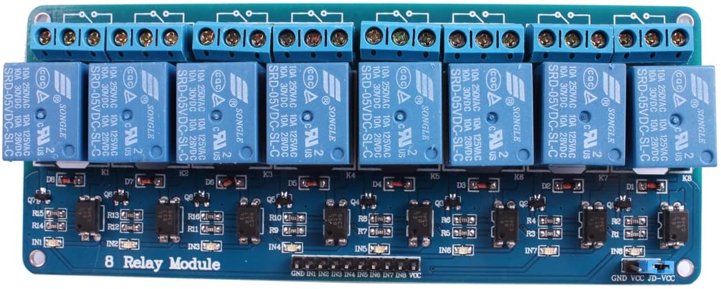
- Multi-channel relay module (2, 4 or 8 channel relay module)
Principle of operation
The relay consists of a solenoid and a mechanical contactor. When the current is high enough on the input terminal, the solenoid becomes magnetized which forces the contactor to close the power circuit. The multi-channel modules, as the name suggests, have several relays, which allows you to control different electrical devices.
Scheme
The 4-channel relay module has one row of input pins. The GND pin connects to the ground of the power supply and to the ground of the microcontroller. If the grounds are not connected correctly, the control signals will not be taken into account. The VCC pin connects to the 5V of the power supply and the INx pins are connected to the microcontroller outputs.
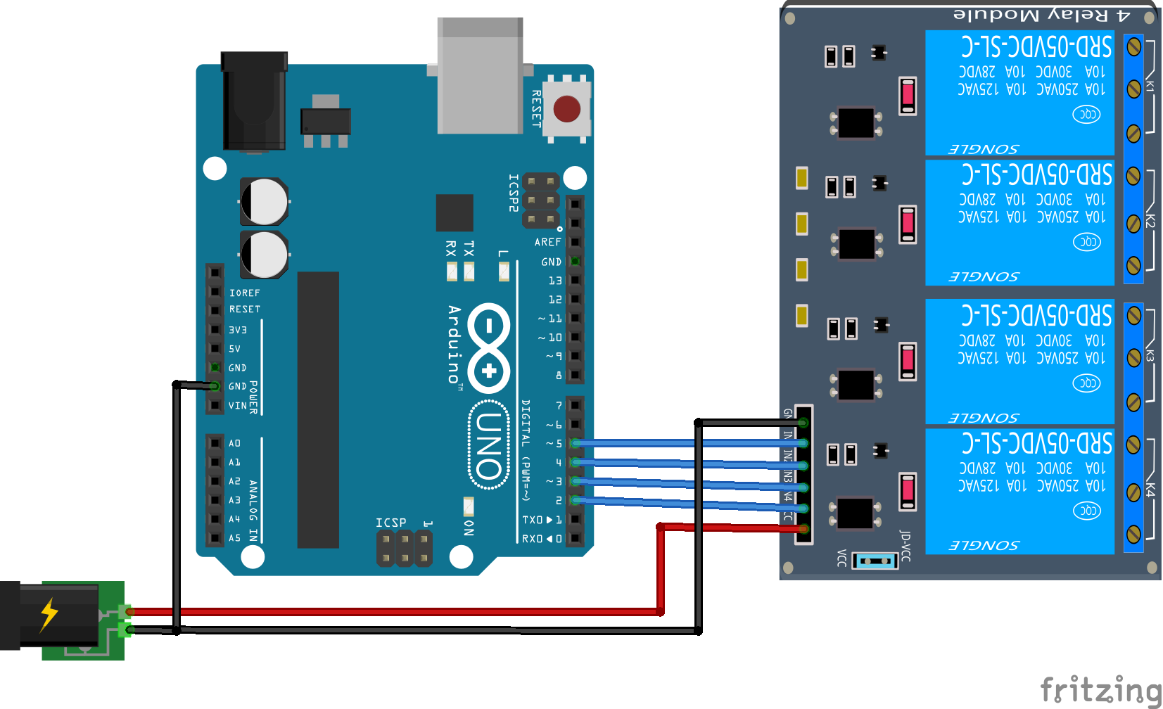
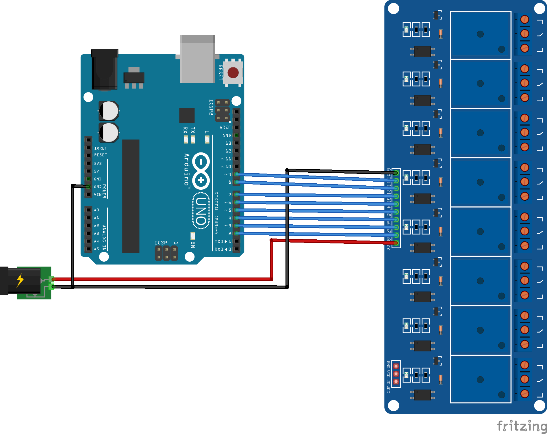
The connections are similar for 2 and 8 channel modules.
Code
To drive the multi-channel relay module, we will create a loop on the microcontroller outputs to activate or deactivate the relay. The code is very similar for 2, 4 or 8 channel relay modules.
//Constants
#define NUM_DO 4 //8

//Parameters
const int digPin[NUM_DO] = {2, 3, 4, 5}; //{2, 3, 4, 5, 6, 7, 8, 9};

void setup() {
  //Init Serial USB
  Serial.begin(9600);
  Serial.println(F(" Initialize System "));
  //Init pwm output
  for (int i = 0; i < NUM_DO; i++) pinMode(digPin[i], OUTPUT);
}

void loop() {
  for (int i = 0; i < NUM_DO; i++) {
    digitalWrite(digPin[i], HIGH);
    delay(500);
    digitalWrite(digPin[i], LOW);
    delay(500);
  }
}
Result
Once the relay module is plugged in and the code is uploaded, the LEDs and relays should turn on and off one after the other.
Applications
- Create a home automation system
Sources
Retrouvez nos tutoriels et d’autres exemples dans notre générateur automatique de code
La Programmerie



Hello,
you can make an array containing the enable state relayEnabled={1,0,1,0,1,0,0,0};
if(relayEnabled[i]) activateRelay(i);