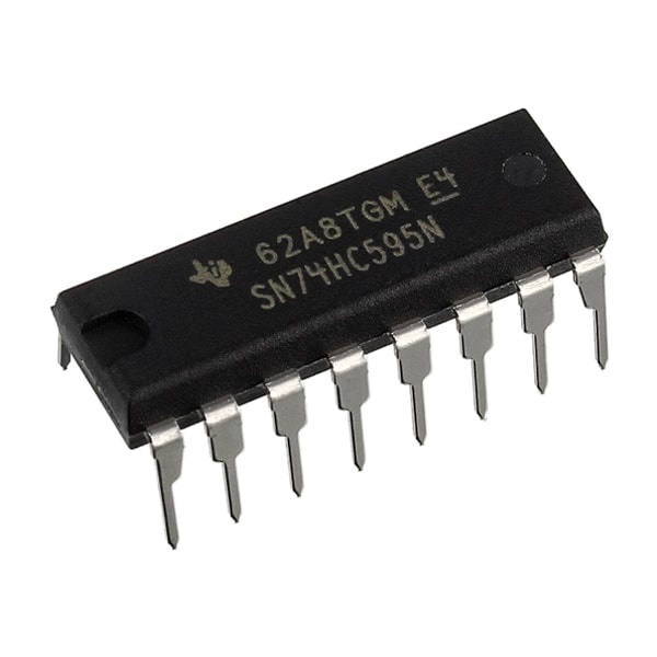
The shift register is an integrated circuit consisting of logic circuits in series that can store high or low states. It can be used to drive LEDs or to retrieve the state of several sensors.
Hardware
- Computer
- Arduino UNO
- USB cable A Male to B Male
- Shift Register 74HC595
Principle of operation
The shift register is an electronic component containing synchronous flip-flops. These are logic circuits that store a high or low state (such as a bit) connected by the same clock. The shift principle comes from the fact that each memory is written or read bit by bit.
In the case of the 74HC595 shift register, the parallel outputs will deliver a voltage of 5V in the high state and 0V in the low state.

Schematic
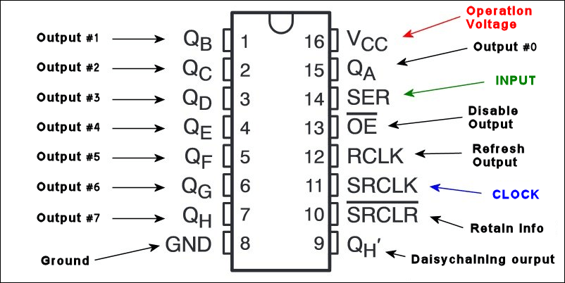
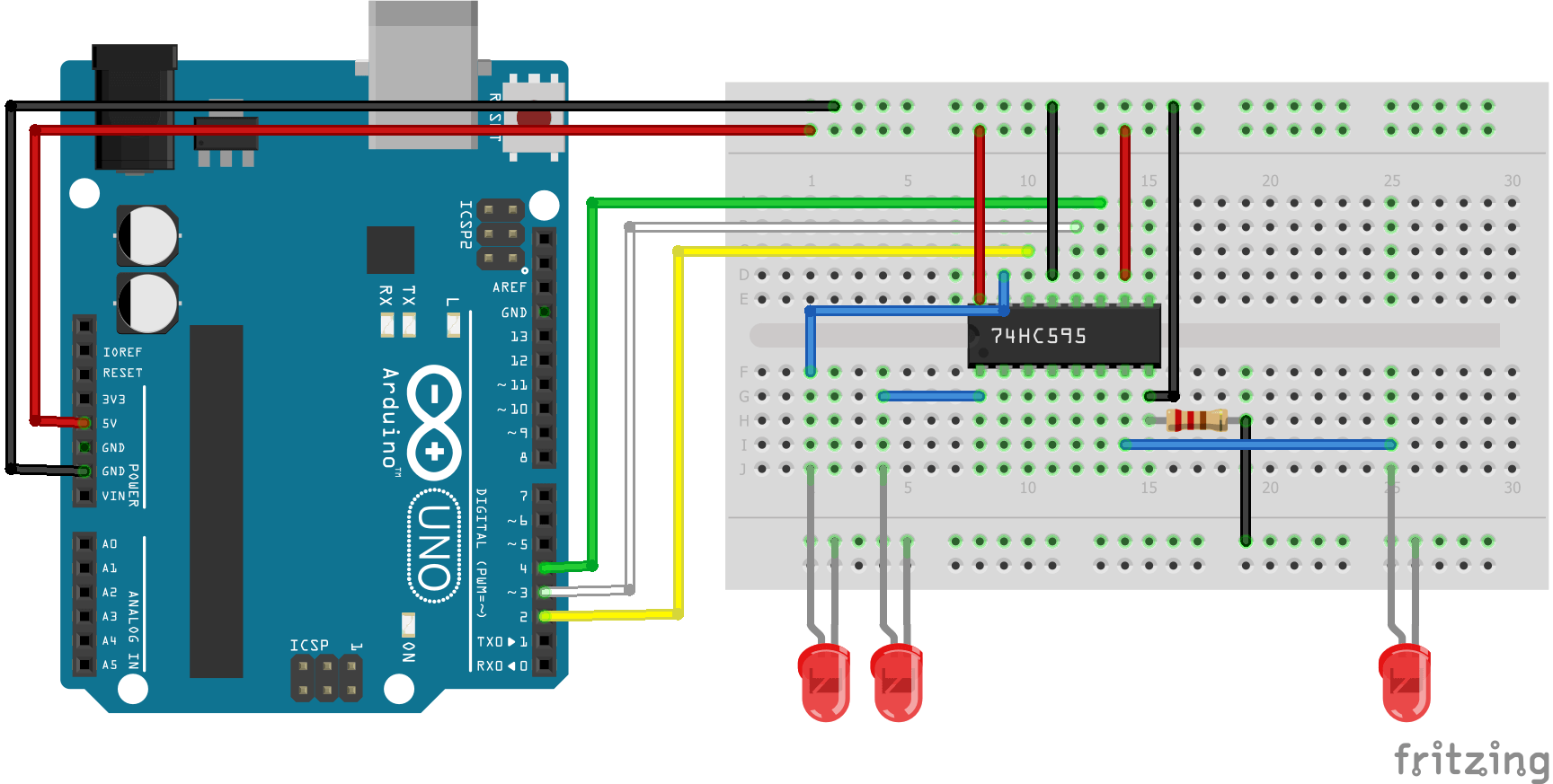
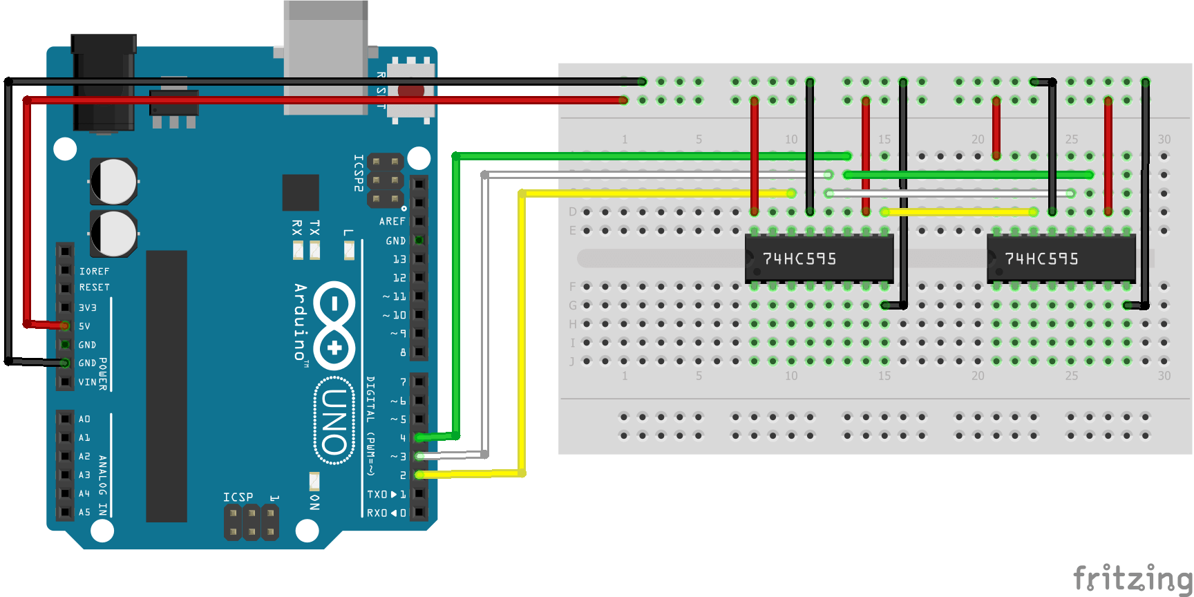
The shift register requires 3 output pins from a microcontroller. It is possible to manage several registers connected in series.
- GND integrated circuit ground
- Vcc power supply pin. Usually connected to 5V
- SH_CP or RCLK shift register clock input. The register clock signal that determines whether or not to write to the memory
- ST_CP or SRCLK storage register clock input. The storage clock signal that defines in which memory to read or write.
- DS or SER serial data input. Signal containing the data to be registered (UP or DOWN)
- Q0-Q7 parallel data output. Shift register output pins
- OE Output enable, activates LOW. Pin connected to GND to activate the outputs.
- MR Master reset, active LOW. Reset pin. Connected to 5V
- Q7′ serial data output (pin used only if several registers are connected in series)
Code
To communicate with the shift register, we will juggle its input pins. To come to write into the register we need to put the RCLK pin down. To write into the flip-flops we need to set the storage clock down. With each clock pulse, we will switch to the next flip-flop. To simplify our code, let’s define this procedure in the writeRegister() function.
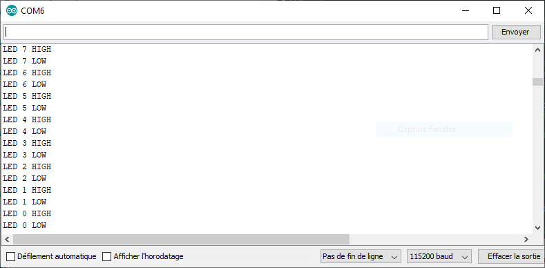
To show the principle of the shift register, a common example is to connect leds to its outputs which we are going to make flash one after the other.
//Constants
#define number_of_74hc595s 1
#define numOfRegisterPins number_of_74hc595s * 8
#define SER_Pin D1
#define RCLK_Pin D2
#define SRCLK_Pin D3

//Variables
boolean registers [numOfRegisterPins] ={0, 0, 0};

void setup(){
//Init Serial USB
Serial.begin(115200);
Serial.println(F("Initialize System"));
//Init register
 pinMode(SER_Pin, OUTPUT);
pinMode(RCLK_Pin, OUTPUT);
pinMode(SRCLK_Pin, OUTPUT);
}

void loop(){
writeGrpled();
}

void clearRegisters(){/* function clearRegisters */
//// Clear registers variables
for(int i = numOfRegisterPins-1; i >=  0; i--){
  registers[i] = LOW;
}}

void writeRegisters(){/* function writeRegisters */
//// Write register after being set
digitalWrite(RCLK_Pin, LOW);
 for(int i = numOfRegisterPins-1; i >=  0; i--){
  digitalWrite(SRCLK_Pin, LOW); int val = registers[i];
  digitalWrite(SER_Pin, val);
  digitalWrite(SRCLK_Pin, HIGH);
}
  digitalWrite(RCLK_Pin, HIGH);
}

void setRegisterPin(int index,int value){/* function setRegisterPin */
////Set register variable to HIGH or LOW
registers[index] = value;
}

void writeGrpled(){/* function writeGrpled */
//// blink leds
for(int i = numOfRegisterPins-1; i >=  0; i--){
   Serial.print(F("LED "));Serial.print(i);Serial.println(F(" HIGH"));
   setRegisterPin(i, HIGH);
   writeRegisters();
   delay(200);
   Serial.print(F("LED "));Serial.print(i);Serial.println(F(" LOW"));
   setRegisterPin(i, LOW);
   writeRegisters();


}
}
Results
Applications
- Manage up to 8 LEDs or sensor with three pins of a microcontroller
- Manage a 7-segment display or more
Sources
- https://fr.wikipedia.org/wiki/Registre_%C3%A0_d%C3%A9calage
- https://fr.wikipedia.org/wiki/Bascule_(circuit_logique)
- Programming with Arduino
Find other examples and tutorials in our Automatic code generator
Code Architect
